Triac Operation
January 2003
The triac (more technically known as the bidirectional triode thyristor) is an electronic switch and is sort of an electronic equivalent of a relay/contactor. But instead of a coil which is energized the triac has a gate which is current triggered to make the triac conduct and turn on the load. Unlike a relay or contactor the triac has no moving parts. Therefore, there are no contacts that can pit and burn, no contact bounce, no arcing, and absolutely no noise.
Like transistors triacs are three terminal devices. They're even packaged similarly (TO-92, TO-220, etc.). But unlike the transistor the triac is not an ampliflier, merely a semiconductor switch. It has only two states: conducting and nonconducting.
A triac can conduct both ways. Therefore, it can switch alternating current. Its cousin the silicon controlled rectifier (SCR) is like half a triac because it conducts only one way. On the SCR the two terminals to which the load is connected are called cathode and anode. Because the triac conducts bidirectionally calling the terminals cathode and anode would be senseless. Therefore, they are known as MT1 (main terminal 1) and MT2 (main terminal 2) instead. The terminal into which the signal is fed to make MT1 to MT2 conduct is known as the gate.
Apart from its current rating, each triac has a specific breadover voltage. With the gate open, this is the minimum voltage between MT1 and MT2 at which the triac will begin conducting—acting like a closed switch. Normally we don't subject a triac to its breakover voltage. Rather, to turn a triac on we pass a small amount of current (<100mA) through the gate to MT1 or from MT1 to gate. Hence, when choosing a triac we pick one whose breakover voltage rating is higher than the peak (not rms!) voltage of our AC line. On a 240VAC line peak voltage is 340V, so a commercially available triac with a breakover voltage of 400V will do. Choosing one with an even higher breakover voltage rating, say 600V, is fine and will offer greater margin, although such a device will cost more.
The most important aspect of triac operation is gate triggering. There are several ways to trigger a triac. But once a triac is conducting gate current can be removed. The triac will continue to conduct until the end of the particular half cycle. If we are switching AC a triac will naturally revert to its nonconducting state within half a cycle of removing gate current. If, however, we use a triac to switch DC, removal of gate trigger will not turn the triac off. As in SCR operation other means of turning it off is necessary. This means that when we remove gate trigger from a triac we are technically not switching the triac off. Rather, the triac actually turns off when the alternating current crosses the zero point. When the current passing through the triac drops below the holding current the triac goes into its nonconducting state. In order to keep a triac continually conducting we have to trigger the gate every half cycle. Or we can apply a continuous DC signal to the gate. Either way the triac will be kept conducting continuously.
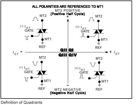
When triggering triacs we need to consider in which quadrants the triac will be operating (see diagram below). If triacs are new to you then the diagram may be a little daunting. These quadrants take a little getting used to. Just remember they are related to but are not the trigonometric quadrants of mathematics. Instead the quadrants refer to the four combinations of the polarites of gate current and MT2 with respect to MT1. The x-axis denotes the gate polarity while the y-axis denotes MT2 polarity. All polarities are with respect to MT1. Since the gate and MT2 polarities are independent of each other and can be either positive or negative with respect to MT1 we have four possible combinations. We designate as quadrant 1 the situation when both gate and MT2 are positive. When the gate is negative while MT2 is positive we call this quadrant 2 operation. When both gate and MT2 are negative with respect to MT1 this is known as quadrant 3 operation. And lastly, when gate is positive when MT2 is negative we are operating the triac in quadrant 4 mode.

It is important to remember that a triac does not have to operate in all four quadrants. Nor does the triac go through all the four quadrants for each AC cycle. In fact for a given circuit a triac usually operates in only two quadrants. And operation in 2 quadrants is the bare minimum since we are working with alternating current and so MT2 will be positive for one half cycle and then negative with respect to MT1 the next half cycle. For example, when the triac is triggered with a continuous DC signal the triac will be operating either in quadrants 1 and 4 or in quadrants 2 and 3. This is because the gate current will always be either be positive with respect to MT1 (Q 1 & 4) or always negative (Q 2 & 3).
With triac optocouplers as triggering device the triac is triggered by alternating positive and negative currents (see optocoupler circuit in the section Solid State Relays). This is called "in-phase triggering" since gate polarity with respect to MT1 always follows that of MT2 polarity vs. MT1. Therefore, the triac operates in Quadrants 1 and 3.
With continuous DC triggering, gate voltage with respect to MT1 will either be always positive or always negative. If positive, the triac will be operating in Quadrants 1 and 4. If gate to MT1 voltage is always negative then triac will be working in Quadrants 2 and 3. In other words, when the gate is sourcing current (trigger current always flows from gate to MT1) then the triac is operating in Quadrants 1 and 4. When the gate is sinking current (current flows the more positive MT1 to gate) then the triac is operating in Quadrants 2 and 3.
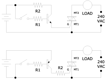
We can design a circuit to trigger the triac with either positive or negative DC gate current. The circuits below show how an NPN and a PNP transistor can trigger a triac. When the switch is closed the transistor is turned on and allows current through to trigger the triac. Because the gate in either configuration is always positive with respect to MT1 the triac in both circuits will be operating in Quadrants 1 and 4.

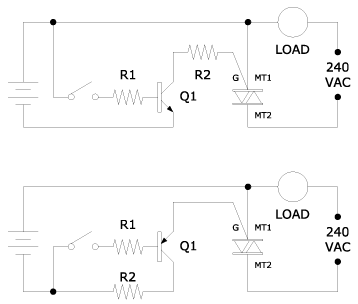
Because triacs require substantially greater gate current for Quadrant 4 operation it is best to operate a triac only in Quadrants 1, 2, and 3. This can easily be achieved by making the positive side of the DC supply the common leg for DC and AC supplies and tying MT1 to it. The net effect is that triac gate will be sinking current to trigger the triac instead of sourcing it—the reverse of the preceding circuits. This means that the triac will be operating in Quadrants 2 and 3. The circuits below illustrate how this can be achieved using transistors.

Of course, in a real circuit the manual switches above would be replaced with electronic ones, like logic gates for instance.
References:
- Definition of quadrants diagram is from triac data sheet by Teccor Electronics, Inc.
- Motorola Thyristor Data, 2nd edition, 1988, Motorola Inc.