The Transistor as a Switch
May 2003
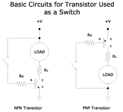
Below are the basic configurations for NPN and PNP transistors when used as a switch. Base is labeled as B, collector as C, and emiiter as E. An NPN transistor switches on when base to emitter voltage is positive. A PNP transistor on the other hand switches on when base is more negative with respect to the emitter. In the diagrams below LOAD is assumed to be current-driven and non-resistive (e.g. LEDs). If LOAD were resistive then RL would denote its internal resistance

In order to successfully use a transistor as a switch it is necessary to adjust the amount of base to emitter current depending upon the amount of collector current that the load requires. Too little base current and the transistor will not be fully switched on--it will not be saturated. Too much base current and the transistor will be overdriven and unnecessary power will be wasted.
In order to compute for base current (and thus the resistor necessary) we need to know something about the transistor we're using. The most important characteristic we need to know is its current gain. Other useful and sometimes important properties are a transistors maximum allowable collector current, maximum allowable power dissipation, collector-emitter voltage drop at saturation, base-emitter voltage drop at saturation, maximum allowable base current.
The relation between base current and collector current is as follows:
IC = IBhFE
IB = (VCC-VBE) / RB
where
IC = collector currentVCC = supply voltage
VBE = base to emitter voltage drop at saturation
RB = current limiting resistor for base
hFE = minimum current gain of the transistor
RL = current limiting resistor for load
Therefore:
RB = [(VCC-VBE)hFE / IC]
Maximum collector current as determined by base current must be greater than the current required by the load. This is necessary in order for the transistor to be in saturation mode. If not, the voltage drop across the collector-emitter will be greater than the minimum (typically 0.2V for small signal transistors). The greater the voltage drop across the collector-emitter the more power is dissipated by the transistor and the less the voltage there is across LOAD. A transistor in such a state is said to be operating in the active region, and is acting like a partially on switch. This is desired when the transistor is being used as an amplifier but usually is undesirable when used as a switch. In the latter case we operate the transistor either to saturation or to cutoff (i.e. base current = zero).
When using the circuits above the manual switch in the diagram will usually be replaced with an electronic one. For instance logic gates or outputs of voltage comparators would be used to switch the transistor on and off.
Reference:
- Solid State Pulse Circuits, David Bell, 1981