Long Duration Timer (Monostable Multivibrator)
December 2002

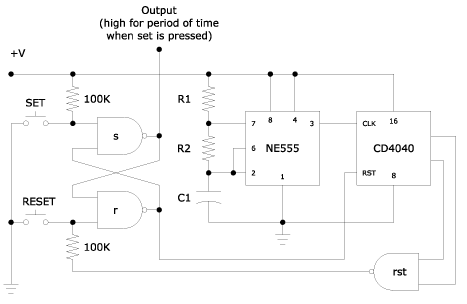
How long is long? Well, the above timer can give periods as long as weeks, and then some. It is based on the NE555 timer wired in astable mode whose output becomes the clock input for a ripple counter (the 12-stage CD4040 in this case). In astable mode the 555 will produce a constant train of square waves—the perfect clock input for the ripple counter. The speed at which the counter counts is directly proportional to the clock frequency. Therefore, if we make square wave frequency slow enough we slow down the rate at which the counter counts.
As you may already know the NE555 can be directly wired as a monostable multivibrator (otherwise known as a one-shot). The problem with such a circuit is that it necessitates using very large value resistors and (electrolytic) capacitors. To get a time period of 1 hour for instance we would need a 7Mohm resistor and a 470uF capacitor (other RC combinations are possible of course). Moreover, it is difficult to calibrate such a timer because of the long time periods (minutes or hours) involved. And given that electrolytics have notoriously wide tolerances such a long duration timer will be quite inaccurate. Therefore, rather than use a brute force approach, we resort to counting (stable and regular) clock pulses and then "adding" them up to get the time period we're after.
Here's how the circuit works:
NAND s and NAND r form a simple RS latch whose outputs starts/stops the counting process as well as controls whatever device we're turning on. SET and RESET should normally be high. At the start output of NAND s is low while output of NAND r is high. With the latter high the counter is placed in reset mode, so that even as the NE555 is continually feeding it a clock signal the counter will not begin counting. When SET goes low momentarily output of NAND s goes high and output of NAND r goes low. They stay as such when SET goes high again. Reset input of counter CD4040 goes low and therefore it begins counting clock pulses. When the counter reaches a predetermined count inputs to NAND rst will both go high and its output will go low. This will trigger the output of NAND r to go high and output of NAND s to go low. High output of NAND r will reset the counter to zero. NAND rst output will then go back high again. The latch will then be ready for another cycle. Making SET low any time while counting is ongoing does not affect the count. But SET must go high before counting is over.
Which outputs of the CD4040 should we use? That depends on the time period we're after and the frequency of the clock input.
R1, R2, C1 are chosen to establish the square wave frequency fed to clock input of CD4040. Refer to the manufacturer's data sheet on how to compute for values of R1, R2, and C1. For a clock frequency of 1 cycle per minute, time periods of more than 60 hours is possible. For the NAND gate the CD4011 Quad 2-input NAND gate may be used if only 1 or 2 outputs from the CD4040 will be needed. A 3-input NAND gate IC may also be used if a more specific combination of outputs from the CD4040 is necessary.
Instead of a manual momentary N.O., switch SET may be replaced with a variety of switches—photoelectric, limit switch, etc. Manual reset switch may be dispensed with if not necessary. Power supply voltages may range from 5 to 15VDC. Power supply should be regulated as much as possible.
As you may have noticed there is no output amplifier. All that is shown above is the control circuit. An NPN transistor will be needed to drive any practical load, such as a relay or triac which would then switch on the AC load. The solid state relay (SSR) described in the foregoing section is one such output amplifier that can be adapted to our timer.
A Better Version
Our timer above is dependent upon an RC circuit. This translates into inaccurate timing. In order to obtain an accurate clock frequency we need more stable sources. One option would be to use the AC power line as a more or less stable frequency source. Alternating current is usually 50 or 60 Hertz. One such circuit using a 60Hz AC line is shown below.

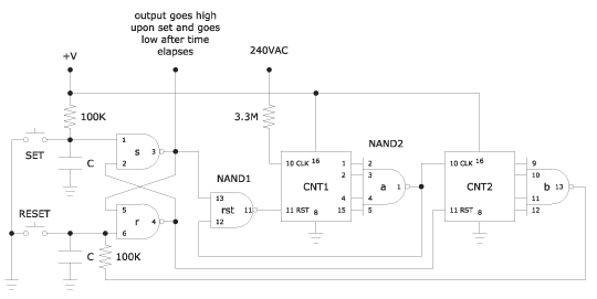
CNT1 is a ripple counter, such as the CD4020, which has outputs for the binary equivalent of 7,200 counts. CNT2 may be any ripple counter as long as it has enough stages and has outputs for the desired time period. The CD4040 would be one choice if outputs of all stages are needed. NAND1 is a quad 2-input NAND IC such as the CD4011. NAND2 is a dual 4-input NAND IC such as the CD4012.
Note that one leg of the AC line is connected to the clock input of CNT1. A 3.3Mohm resistor limits the current going into the CMOS IC to well below 10mA (absolute maximum). The other leg is connected to ground. The above circuit will also work with a 110VAC input.
CAUTION: Working with AC mains is very dangerous. Be very careful and be sure you know what you're doing. Do not touch any part of the circuit when it's powered up. Be careful not to accidentally earth any conductors.
For some reason CNT1 counts 120 cycles instead of 60 (on a 60hz power line). Therefore, NAND1 must be set to count 120 Hz x 60 sec = 7,200 cycles to measure one minute.
When SET goes low momentarily NAND1.s output goes high and stays high. Reset pin of CNT1 then goes low and allows CNT1 to begin counting AC line frequency. If RESET goes low momentarily output of NAND1.s goes low and output of NAND1.r goes high, resetting CNT1 and CNT2. Both counters will remain in reset mode until SET once again goes low momentarily.
When CNT1 has reached the desired count normally high output of NAND2.a will go low momentarily. This pulse serves as the clock input of CNT2 as well as resetting CNT1. CNT2 will advance one count every 60 seconds. When NAND2.b output goes low the latch circuit is reset and CNT1 is reset, terminating all counts.
Maximum time that can be counted given a 4-input NAND is 64 hours.