Transformerless Power Supply
October 2002
Electronic enthusiasts will tell you that for any project one is always faced with the mundane but essential task of designing and constructing a power supply. It's a must unless you're working solely with AC mains voltage.
Here are a couple of simple designs which you can use if you need only several tens of milliamperes of current. They can probably be used to source up to around 100mA if you either (1) use a Zener diode voltage less than 6V or (2) use one that has a power rating greater than 1 Watt.
Principles
The theory behind creating a transformerless power supply is to have one or more Zener diodes set the supply voltage for our circuit and to have a means of limiting the current supplied to the Zener so as keep its power dissipation within its maximum rating.
In principle we can use resistors to limit the current flowing through the Zener diode (which is our crude voltage regulator), but because most of the voltage drop will be across this resistor it would need to have a high wattage rating if we needed say more than a couple of milliamps. Let's say we needed 10mA of current. With an AC mains voltage of 240V the approximate power dissipation (as heat) of the resistor would be (240)(.01) = 2.4W. As you can see using a resistor is not very practical and certainly very inefficient since it wastes more power than it supplies. Even something as simple as driving one LED would require around 10mA which translates into around 20mW of power. At 2.4W the resistor is dissipating some 120 times more power than the lamp!
Because a capacitor allows current to flow but poses a resistance as well when connected to an AC source we can use this phenonmenon, known as capacitive reactance, to do the work of a resistor without worrying about its power dissipation. Capactive reactance is a resistance and therefore also measured in ohms. It is a function of capacitance and the frequency of the alternating current:
XC = 1/(2πfC)

where
XC = reactance in ohms
f = frequency in hertz
C = capacitance in farads
Since 2π is a constant we can simplify the equation to:
XC = 0.159/(fC)And if working with common AC mains with a frequency of 60Hz and if capacitance is given in microfarads the equation can further be reduced to:
XC = 2653/C

for an AC with a frequency of 60Hz
with C in microfarads
This means that as we add more capacitance reactance is reduced. At 1 microfarad reactance = 2653 ohms. With 2 microfarads reactance is halved.
Half Wave Supply
CAUTION: Working with AC mains is very dangerous. Be very careful and be sure you know what you're doing. Do not touch any part of the circuit when it's powered up. Some portions are directly connected to the AC mains. And remember the capacitor may still be substantially charged even after you've unplugged the circuit. Discharge it using a 1Mohm resistor.
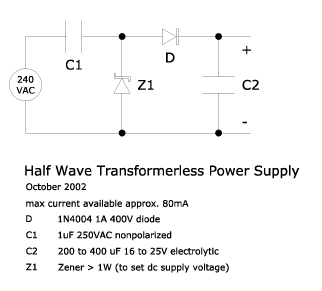
Here is the schematic for a very simple half wave transformerless power supply:

By using a large enough C2 the above supply will be able to power circuits that run satisfactorily on an unregulated supply.
It is very important to consider how much power will be dissipated by the Zener. Remember that all else constant using a higher voltage Zener means proportionally increasing the power dissipated by that device. In the circuit above a 12 Volt Zener would dissipate a maximum of (12)(.09) = 1.08W of heat when there is zero load. This is for one half cycle, when the Zener is reverse biased. In the next half it will be dissipating much less since the voltage drop across the Zener when it is forward biased is only about 1 Volt. A 6V Zener would, therefore, dissipate only half the power. This means a 1 Watt Zener would more than suffice for this circuit. Because of this constraint this power supply is limited to around 100mA and to voltages of around 12 Volts. If the circuit can use voltages lower than 6V or if Zeners with power ratings greater than 1W can be obtained then it is safe to proportionally increase the capacitance of C1 to provide more current.
Finally include a (glass) fuse in series with one of the AC lines as protection.
Full Wave Supply
CAUTION: Working with AC mains is very dangerous. Be very careful and be sure you know what you're doing. Do not touch any part of the circuit when it's powered up. Some portions are directly connected to the AC mains. And remember the capacitor may still be substantially charged even after you've unplugged the circuit. Discharge it using a 1Mohm resistor.
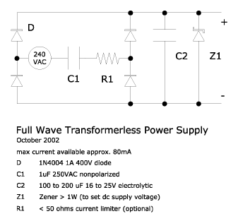
Here is the schematic for a full wave transformerless power supply:

Because this is a full wave power supply, capacitor C2 need not be as large as in a half wave supply.
As in the half wave supply pay careful attention to power dissipated by the Zener lest its rating be exceeded. In addition note that the Zener in this circuit is always reverse biased and so is dissipating the same amount of power in both half cycles. Given the same C1 the Zener in this circuit will actually dissipate more average power than one in the half wave supply
Finally include a (glass) fuse in series with one of the AC lines as protection.
References:
- http://www.geocities.com/tjacodesign/index.html
- http://www.aaroncake.net/circuits/supply5.htm
- Bernard Grob, Basic Electronics, 5th ed., McGraw-Hill, 1984