Using a Flashing LED as a Pulse Generator
May 2003
Usually we force buzzers, lights, etc. to operate intermittently by using an astable circuit to produce a square wave <5 Hz. A 555 timer IC for instance can be used to produce such a rectangular (pulse) waveform.
I just discovered that there are LEDs that flash on their own. They blink on and off without any special circuitry other than the mandatory current limiting resistor. The flashing LED I have on hand has a part number 5R3HCBL-2. Unfortunately I'm not certain who the manufacturer is (probably a company called Kome). Examining the LED with a magnifying lens (the one I obtained is made of clear epoxy) I discovered that it has an IC chip embedded inside, which presumably is the control circuitry that allows the LED to flash.
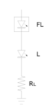
I then wondered whether I can connect an ordinary non-flashing LED in series and make both LEDs flash.

Using the above circuit I found that indeed an ordinary LED will blink along with the flashing LED. In the diagram FL denotes the flashing LED. I've drawn it here with a box around the symbol of an ordinary LED to denote that it is in essence an integrated circuit. This is actually an important fact to remember since the IC has a maximum operating voltage. Spec sheet for another flashing LED (not the one I tested) indicates that its absolute maximum voltage is 14V (this will of course vary on the make and manufacturer). Thus, unlike ordinary LEDs which can withstand several hundred volts (foward biased of course), the flashing LED will be destroyed even by some power supplies. It is important to keep this in mind since these LEDs externally look exactly the same as ordinary ones.
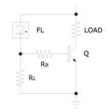
After succeeding with the circuit above I then wondered how I can use a flashing LED to switch a transistor on and off so that I can in turn switch other (bigger) loads such as buzzers, optoisolaters, etc. I came up with the circuit below.

RL is the current limiting resistor for FL. RB meanwhile is the current limiting resistor for the the base-emitter of NPN transistor Q. Note that RL and RB are in parallel and determine the actual amount of current through FL. If the value of RB is less than 20% of RL then it can be disregarded in computing for RL. RB should be chosen in accordance with the current gain of the particular transistor and the amount of collector current required.
When FL is on the voltage across RL switches Q on. When FL is off, however, base of Q is effectively shunted to ground, thus turning Q off. The end result is that LOAD goes on and off in phase and at the same frequency as FL.
If necessary, a PNP transistor can be used instead to switch LOAD on when FL is off.