555 Timer as a Latch
May 2003
When is a timer not a timer? When it's not configured to monitor charging or discharging capacitors.
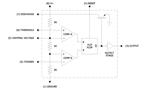
The 555 timer basically consists of two voltage comparators and a simple RS latch. The following functional block diagram will help explain how a 555 works. Numbers inside parentheses refer to the IC pins.

As you can see Comparator A is referenced at 2/3 of supply voltage V+ while Comp B is referenced at 1/3 V+. This means that when Comp B detects a voltage that's below 1/3 V+ at its inverting input (input with negative sign) Comp B will set the flip-flop which then forces the output of the 555 go high. On the other hand when Comp A detects a voltage that's greater than 2/3 V+ at its noninverting input Comp A will reset the flip flop, switch the discharge transistor on, and force output pin3 to go low.